Fig. 1. Fluidmechanics interpretation for external beside forces of wave nature,
illustrating rolling and driftage minimization mechanism for antique ship with roundish tumblehome boards (A) and impact forces to hull of modern ships (B).

Vasily N. Khramushin
Special Research Bureau for Automation of Marine Researches, Far Eastern Branch
of Russian Academy of Sciences
Yuzhno-Sakhalinsk, Russia
ABSTRACT
The Russian Far East sea domains are characterized by a high stormy activity, which greatly increases the seakeeping requirements for an ocean ship. The research urgency is caused by a large-scale development of oil and gas resources on the Sakhalin shelf. Absence of developed ports-shelters along the north-eastern coast of Sakhalin raises the necessity of formation of the sea phenomena monitoring systems, support of efficiency and safety of navigation, optimization of design solutions for vessels of improved seakeeping.
Researches aim is a searching of technical decisions for a non-contradictory principles to optimization of hull form and naval architecture, founded on technical-history analysis of projects of the known ships, and on seamanship experience in heavy conditions of sail, which is substantiated by mathematical researches and towing basin experiments.
KEY WORDS: Vessel, non-contradictory design, seakeeping, tumblehome, ship wave radiation, stormy wave influence, safety sailing.
INTRODUCTION
Approaches to search of basic design decisions for ships and vessels with improved storm seakeeping are considered. Principles of the non-contradictory optimization of the hull form and naval architecture are developed. They are based on the technical and historical analysis of projects of well-known ships and the seamanship experience under heavy sail conditions and confirmed by the mathematical research and towing basin experiments. Possibility of the essential improvement of propulsion and other nautical qualities of a ship in the storm and heavy sea conditions is shown. A complex of the technical decisions, which have been used to develop a draft of the hull form and naval architecture of optimized universal cargo ship, is offered.
In the first part of work was submitted the technique-historical analysis of representations development about the most seaworthy form of the hull of the ship. The most known ocean ships are examined, because were projected by seafarers knowing assignment of the ship and condition of it navigation. The second part is devoted to the engineering decisions with use of calculus mathematics and geometrical interpretation of the hull form of the ship, as source of wave radiation. The third part begins with designing of the hull form of hypothetical ship models and description of their stability diagrams. These materials anticipate the analysis of propulsive qualities and seaworthiness of the new hull. At the end, there are attempts of drawing up a system of the uninconsistent requirements to appearance of the ship as a whole.
It is known that ancient ships were under construction by navigators and the designing of a new ship was always done, taking into account future mode and area of navigation. It is possible to make the assumption that if the certain design decisions on the hull's form and ship architecture were kept by centuries and were duplicated simultaneously in several countries, it is possible to consider the appropriate ships quite seaworthy or optimum on navigation conditions and good sea practice.
The ancient seafarer-shipbuilders had to give the much greater attention to safety of storm navigating, because rowing paddles are not suitable as movers even at temperate wave roughness, and the squall heavy wind the sail arms become into a source of serious danger. A modern vessel, under condition of maintenance of serviceability of the main engine and steering device, is in a condition to oppose to sea elements capacity of the machines, thus reducing the requirements to storm seaworthiness provided with the form of the hull and superstructures.
The historical evolution of ship architecture is explained by changes in principles of keeping a motion and only partly by condition of shipbuilding technology. Last thesis is convenient for application to analyze seaworthiness of ship's hull from the most ancient times till the beginning of XX centuries (Fig. 1~3). In naval architecture of modern vessels or ships of identical purpose, we can find essential differences in their form of the hull and superstructures, therefore there is interesting realization of the comparative analysis of seaworthy qualities caused by contours of the hull and architecture of superstructures. The urgency of such question is related with fast changes of ideas about the best form of the hull last decades, but for this period there were no changes in principles of seaworthiness or maintenance.
Fig. 1. Fluidmechanics interpretation for external beside forces
of wave nature,
illustrating rolling and driftage minimization mechanism for
antique ship with roundish tumblehome boards (A) and impact forces to hull of modern
ships (B).
Heave pitching give fall off propulsion, hull stabilization, as well as degrading general and longitudinal strength of hull
Fig. 2. Pitch damping decreases by transposition of floating forces
to middle of hull (like body of seagull with extended stems)
It’s doubtless, that in ship hull configuration, what designed in the beginning of XX century was realized conciliatory proposals between submission and an opposition before threat of stormy sea:
Ideal architecture of the hull by all named criteria had cruisers and destroyers constructed at the end of XIX are beginning XX centuries (Fig. 3). Good seaworthiness has a linear ship of that time, which had low and pointed a bow and quarter-deck, which basic surface volumes were going in an average part of the hull. It provided a steady movement on roughness in conditions increased sweeps of extremities.
Fig. 3. «Izmael» type destroyer. The ship can stay on course
by «cut through» stormy waves.
The special requirements of propulsive quality on a stormy ocean were no made to merchant steam vessels, because their main engine was a cumbrous and low power. This vessel has a pointed vertical stem and rounded stern above water on aft. In storm weather this vessel must take a course by a bow to wave and to be kept it by engines and helm driving until improvement of weather.
Geometrical presentation of wave amplitudes function A(l,z) and all of it’s analytical approximations by using physical arguments with natural measurements, such as: l– length of ship waves; z – depth under sea surface; J – direction of ship waves propagation.
Fig. 4. The absolute and ship coordinate systems.
In physical variables the Michel’s integral for wave resistance of ship stayed in next form:
 ,
(1)
,
(1)
where is:
 ;
(2)
;
(2)
 – phase wavelength;
w0 = x0 cosJ
+ y0 sinJ –
angular extent;
 – radius of fluid participants path, etc.
Geometrical interpretation of rising ship waves
Fig. 5. Scheme of reflected radiation of free to ship waves
(1). Front of diverging waves, moving (radiated) at the speed of V=V0·cosJ;
(2). Position of waves front, as it were oncoming to ship hull, which
also is stationary in body axis, but is not taken into account in equations;
(3). Direction of ship wave;
(4). Direction of approach as it were external wave,
which: ÐJÎ]-p¤2¸-p] or
ÐJÎ[p¸p/2[.
Fig. 6. Two systems of ship waves are reveal itself in form of free phase
waves and formed by them packages of group wave structures.
(1) Fronts of phase waves with form frequency of k=f(J);
(2) Group system of ship waves, V=V0 cosJ;
(3) Bands of wave packages;
(4) Profile of wave on center plane of hull;
(5) Direction of phase ship wave.
Really conditions of ship waves forming greatly depending from hull configuration.
Fig. 7. Conditions of divergent waves shaping
(1) Adding the amplitudes of wave pulses, radiated from different
points of ship outer plating simultaneously;
(2) The wave is not formed if tangent to front surfaces does
not fall into sector ÐQ.
Fig. 8. Ship waves arise near of hull surfaces on {A : B} area with strong
Doppler’s frequency garbling
One of the main conditions for hull influence decreasing from stormy waves is an practical optimization of hull configuration for minimum wave radiations on all velocities, including supercritical high, and for all draft, which is hull drying in a storm heaving process. Shown on Figs. 5~8 principles of shaping ship waves can be used in design prospecting at building of optimum hull configuration.
In practical sea storm navigating are traditionally used the models of roughness, which represent as interaction of several independent systems of waves (Fig. 9): 1) wind wavily is complies with direction of wind action, height of waves can be at most big; 2) two-three systems of swell waves, being echoes earlier passed or remote storms, at length of swell waves usually greatly more, than wind waves, but steepness –less.
For computer simulating of heavy storm pictures on open sea are possible to try to impose with each other group cellular structures of wind and swell waves, which differ by length and direction of their spreading. Got a wave picture wholly corresponds to the observations for real storm in open sea. Are they easy discover on short and steep of wind waves, but for finding the background swell waves the navigator must to rise on upper bridge. At night of no parameters of sea wavily to define practically impossible.
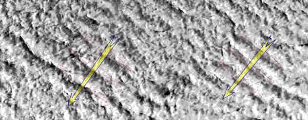
Fig. 9. 3-D model of heave sea surface, presented
by imposition of three independently existing cellular-group structures of wind
and swell waves: 1) wind waves: l=60 m,
t=6,2 s, h=7,2 m, go by azimuth A=250°;
2) first swell waves system: l=100 m,
t=8 s, h=6 m, A=210°; 3) and second:
l=160
m, t=10 s, h=5 m, A=270°. Isolines of sea level thru 2 m and profiles of waves
is shown. The course A lead to headwind, another courses on 15+, 30+ and 45+ at
angle of waves. The profiles of waves are shown in lower part of drawing on noted
courses.
At choice of stormy ahead and course of ship usually oriented only on particularities of wind waves, which estimated by white wave crests, observed through spray guard on wheelhouse illuminator. At night time safety of stormy sail depends only from navigator officer and helmsman intuition, which absolutely nothing not known about sea condition, except estimations of winds force and directions. Under such navigational condition, certainly, traditional vessels have not possibility to efficient sail by free course in stormy sea, appears serious danger of shipwreck. Undoubtedly that so "night blindness" conditions for sail safety turn is accompanied greater overloading to the helmsmens machines and screw propellers shafts.
Exists two way for maintenance efficient and safe storm navigating. This or foresight to absolute passivity of ship hull to any influences from stormy waves, or giving to ship to very high maneuverability and decent propulsion sufficient for quick and well-timed runaround of shattering storm waves blows. First passive method must usable to large vessel, and only small ships and cutters can active confront maneuvering under heavy sea.
Effective way for reached a passive storming is the reduction of value and inertia moments of area for all waterlines, which drayed in process of stormy pitching and heaving, on begin stage of ship design.
Form configuration of SIW hull model was extrapolated (intensified) from nautical qualities of speed-ships from end XIX to begin XX ages.
|
Form of hull characteristics: L = 2.6 / 2.32 m. |
Fig. 10. The experimental model of heavily-loaded vessel
with exaggerate
qualities of antique ships, got on results of computing optimization by minimum
of wave resistance. The hull configuration to models allows undertaking the towing
experiments in wide range of sea surface boarding.
Main requirements to hull form is:
|
Hydrostatic curves |
Fig. 11. Small inner slope of boards and sharpenning the waterline in
extremities of hull bring about significant reduction of area inertia moments for
the active waterline/
Comparative propulsive and seakeeping experiments
The model SIW has a small waterplane area. For exception of running trim the model was attaching in gravity towing system by means of special gear harness (Fig. 12), carrying in lower of hull the force bearing point.
Fig. 12. Scheme of SIW model gear. (1) Vertical pusher bar; (2) Horizontal
lever; (3) Support platform; (4) Pusher bar bed; (5) Gyrovertical;
(6) Signal flag
1. Tests on calm water surface
Building a comparative towing characteristics (Fig. 13) for estimation of wave resistance of SIW ship model, as a result which was expected the essential advantage on velocities for model motion, which corresponding to Froude number more then Fn>0.5.
Fig. 13. Factors of residual resistance: 1. Standard model of
«Victory» vessel, d=0.675;2. Model of fast vessel of
«60 series», d=0.572;3. SIW,
d=0.827,
T=135 mm; 4. T=125 mm; 5.
DT=40 mm to stern; 6.
towing to aft ahead; 1÷3 - in the Froude’s gravity system;
4÷6 - under towing trolley.
Model of tumblehome vessel has confirmed computational optimization results (Fig. 13). Observe a small ship wave radiation and greatly smaller wave resistance on a fast speed towing, that corresponds to the weakening of interaction between ship hull and long stormy waves.
Fig. 14. Diversion waves interpreting by means
of water whirl, given rise at near of bow shoulder plating.
Sharp distinction of residual-resistance between models on velocities of order Froude’s number Fn=0.3 is explained by vortices particularities in the approach flow in area of hull bow shoulder (Fig. 14). Within reason from heuristic hypotheses the generation of such vortices is useful for high-speed vessels, so simultaneously such flow along bow shoulder will promotes to considerable pitching and heaving dumping in active sailing on stormy head sea conditions.
2. Test to propulsions and pitching on regular waves
Fig. 14. Relative loss of speed for models in gravity towing system on regular
waves. Upper curves for the force speed ahead; Middle - Full speed; Down
- Half speed. Solid curves for wave amplitude equal to models draft and dashed curves
for wave’s amplitude near to half of draft. Thin (upper) curves for model of high-speed
vessel «60-series» with d=0.572; thick curves - for SIW model.
DV=(Fno–Fnw)/Fno – loss of stormy speed to calm
water towing;
l = g·T2/2p,
– length of progressive gravity waves;
WB=w2·A = 4p2·A/T – acceleration on
peak of stormy wave.
Fig. 15. Pitching acceleration at extremity hull of ship models.
Techniko-history analyze, computational optimization and comparative towing experiments give uniquely determine for primely confirmation an exceed in seakeeping quality of antique ships. Observations for behaviors of free sailing of the SIW model on a heave waves also not reveal dangerous at stormy navigating.
CONCLUSIONS
It is propose to realization optimized (compromised) variant of universal cargo vessel, rescue vessel and another, which satisfying following design requirements:
1. propulsion on heavy waves;
2. pitching and rolling stabilization;
3. safety of storm sailing.
Interdependent rules:
Fig. 16. Design of universal cargo vessel by antique bulbous jars Roman
warship prototype, with tumblehome board at the expense of underwater tweendeck
spaces.
Fig. 17. Design of scientific researches or rescue vessel with hull of
medieval sailing ship prototype, elaborated for need of maintenance of high propulsion
in storm conditions.
ACKNOWLEDGEMENTS
Author sincerely thankful for help and participation in performance the many sailors and shipbuilders, and particularly for A. Kamyshev, D. Bronstein, G. Malenko from Kaliningrad Marine College, A. Kholodilin, A. Achkinadze from Saint-Petersburg Shipbuilding University, G. Bugaev and S. Antonenko from Vladivostok Technical University.
REFERENCES
Proceedings.
The 2-nd Asia-Pacific Workshop on Marine Hydrodynamics
(APHydro-2004)
P.398-402
June 21-22, 2004
Sangnam International House
Pusan National University, Busan, Korea